Coil Nomenclature
Model Nomenclature
| Fluid Coils | 8W24-96-5608T-24.3-H-1.0-R-B | 8 | W | 24 | – | 96 | – | 56 | 08 | T | – | 24.3 | – | H | – | 1 | – | R | – | B |
| ↑ | ↑ | ↑ | ↑ | ↑ | ↑ | ↑ | ↑ | ↑ | ↑ | ↑ | ↑ | |||||||||
| Typical Model Numbers | (a) | (b) | (c) | – | (d) | – | (e) | (f) | (g) | – | (h) | – | (i) | – | (j) | – | (k) | – | (l) | |
| ↓ | ↓ | ↓ | ↓ | ↓ | ↓ | ↓ | ↓ | ↓ | ↓ | ↓ | ↓ | |||||||||
| Steam Coils | 2D16-60-5610F-10.2-H-B | 2 | D | 16 | – | 60 | – | 56 | 10 | F | – | 10.2 | – | H | B |
Descriptions
(a) — Rows in Direction of Airflow
(b) — Coil Type
(c) — Number of Tubes High in Face of Coil
(d) — Finned Length
(e) — Tube O.D.: 55 = Tube O.D. and Spacing (55, 56 or 89)
(f) — Fin Spacing In Fins Per Inch
(g) — Fin Style: T (Turbex), F (Flat) or M (V-waffle)
(h) — Face Area of Coil (sq ft)
(i) — Airflow Direction: H (horiz) or V (vert)
(j) — Serpentine (Circuit)
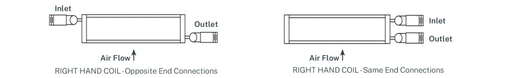
(k) — Coil Hand: R (Right) or L (Left)
(l) — Joint construction: B (Brazed) or W (Welded)
Coil Types
W — Water
E — Evaporator
P — Pitched & drainable
J, X, K — Cleanable plug
Q, Y, R — Removable box header
A — Ammonia Coil
C — Condenser Coil
D — 5/8″ tube distributing steam
H — 0″ tube distributing steam
S — 5/8″ tube blast steam
V — 1.0″ tube blast steam
Other Materials
| Material | 5/8″ or 1″ O.D. Tubes Tube Wall (in.) | Headers | Casing |
| Copper | .025″, .028″, .035″, .049″, .065″ | Types M, K & L tubing | 0.125″ |
| Aluminum | .049″, .065″, .083″ | Sch. 40, Class 200 | .063″ to .125″ |
| 90/10 or 70/30 Copper/Nickel | .035″, .049″, .065″ | Sch. 40, 80 | – |
| Admiralty Brass | .035″, .049″, .065″ | Sch. 40, 80 or 10 GA. | – |
| Carbon Steel | .035″, .049″, .065″ | Sch. 40, 80 or 10 GA. | 16 to 10 GA.* |
| 304 & 316 Stainless Steel | .035″, .049″, .065″ | Sch. 40, 80 or 10 GA. | 16 to 10 GA. |
| AL6XN, Red Brass, Carpenter 20, Incoloy, Hastelloy, Monel, SM0254, Titanium or many other special materials | Contact Factory | Contact Factory | Contact Factory |
Coil Hand is determined by position of outlet connection when facing entering air side.